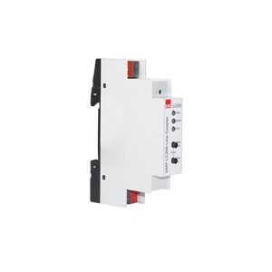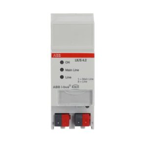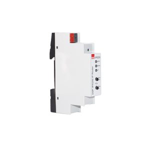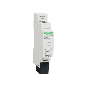












Most KNX projects do not lose money because of the wrong actuator. They lose money because the topology looked “good enough” during tender review — and became impossible to scale during commissioning.
One megabus across three floors. Couplers added only after power alarms. An IP backbone promised in the tender and omitted from the BOM. Those are topology bets, not product mistakes.
In this article, a scalable KNX topology refers to a deliberate map of powered segments, coupler / router boundaries, and backbone medium (TP or IP) that keeps device density, cable plant, and commissioning scope inside defendable limits — so late fit-out does not force a cabinet rebuild.
For the purpose of this guide we group common design approaches into four practical topology patterns we call SCALE-4. These labels (Floor Line, Function Cluster, IP Backbone, Cabinet Star) are a Smartanix naming aid for tenders and training — not official KNX Association terms. The underlying system rules (lines, areas, media, couplers, routers) remain those defined in the KNX System Specifications and related installation guidance.
This guide is brand-agnostic first. Lock the line design, then map couplers and routers into procurement. Pair it with the KNX power budget worksheet (one budget per segment) and the multi-brand BOM template (segment / location on every row).
SCALE-4: a practical naming set for line design
Use one primary pattern per project zone. Mixing is fine — mixing without naming the line / area boundary is not.
- Floor Line (FLP) — one TP line (or clear line set) per floor or wing; line coupler or IP router to the backbone.
- Function Cluster (FCP) — separate TP lines by load or traffic class (dense lighting vs HVAC vs public-area panels).
- IP Backbone (IBP) — IP routers as the area / building spine; short TP lines hang off each router.
- Cabinet Star (CSP) — star or short tree from a technical cabinet inside installation length and power rules — never a building-wide “star of convenience.”
KNX floor line topology
When it scales: multi-floor commercial shells, hotels, and offices with repeating floor plates.
Backbone (TP or IP)
        |
   +----+----+
   |         |
Floor 1   Floor 2   Floor 3
coupler/  coupler/  coupler/
router    router    router
   |         |         |
TP line   TP line   TP line
   |         |         |
devices   devices   devices
- Do: put the line coupler or IP router decision in the BOM before actuator counts freeze.
- Do: keep the riser / backbone medium explicit (TP backbone vs IP).
- Don’t: daisy-chain floors on one TP segment “until we need a coupler.”
What goes wrong: Floor 2 fit-out adds panels; the shared megabus browns out; the team buys a second supply and emergency couplers under time pressure — commissioning stretches and profitability drops.
KNX function-based line design
When it scales: dense lighting floors, mixed VRF gateways, high panel counts in lobbies, or secure-heavy public zones.
                 Backbone / area
                       |
         +-------------+-------------+
         |             |             |
     Lighting       Climate       Panels
     TP line        TP line       TP line
     (+ supply)     (+ supply)    (+ supply)
- Do: isolate noisy or high-chatter clusters when commissioning risk is high.
- Do: document filter intent at the line coupler (which group addresses must cross lines).
- Don’t: invent clusters only to hide an undersized power budget — fix the budget or the density.
What goes wrong: One “everything” line passes tender review, then AC gateways and DALI bridges push traffic and current past what the original design assumed — forcing avoidable redesign.
KNX IP backbone topology
When it scales: buildings with a reliable IP plant between cores, campuses, or long risers where a TP backbone is the weak link.
           Building IP network
                  |
     +------------+------------+
     |            |            |
  IP router    IP router    IP router
  (Floor 1)    (Floor 2)    (Floor 3)
     |            |            |
  TP line(s)   TP line(s)   TP line(s)
     |            |            |
  devices      devices      devices
- Do: treat each router-attached TP side as its own powered segment and current budget.
- Do: lock IP addressing / VLAN / multicast assumptions with IT before award.
- Don’t: omit IP routers from the commercial BOM because “IT will provide something.”
What goes wrong: The tender promised an IP backbone; purchasing ships only TP couplers; site discovers the riser cannot carry the TP plan — costly rework under schedule pressure.
KNX cabinet star topology
When it scales: plant rooms, small wings, retail boxes, or a dense cabinet feeding nearby rooms — inside installation length and topology rules.
              Technical cabinet
              (hub + power supply)
                     |
        +------------+------------+
        |            |            |
     devices      devices      devices
   (nearby)      (nearby)     (nearby)

Annotate: longest cable run + device count
- Do: verify free-topology limits (length, stubs, device count) against manufacturer guidance and KNX installation practice for the cable type you specify.
- Do: keep the star local; promote to floor-line or function-cluster design when “nearby” rooms become another floor.
- Don’t: run a building-wide star from one basement cabinet and call it “free topology.”
What goes wrong: Cable plant exceeds the sketch; intermittent devices appear “random”; the team adds rogue supplies or loops — diagnosability collapses and unexpected procurement follows.
Line coupler and IP router placement rules
| Decision | Prefer | Avoid |
|---|---|---|
| Segment boundary | Named line ID + coupler/router SKU on the BOM | “We will split later if needed” |
| Power | One supply plan per powered segment | Two supplies on one segment without a proper line/area split |
| Backbone | Explicit TP backbone vs IP in tender notes | Unspecified “backbone” that purchasing interprets as free cable |
| Filter / group design | Document which group addresses must cross | Wide-open coupling “to make it work on site” |
| Secure projects | Match secure-capable coupler/router variants to the security plan | Mixing secure and non-secure assumptions after award |
Topology decision checklist
Duplicate into the design review. A blank cell means the topology is not tender-ready.
| # | Check | Owner | Status (Y / N / Hold) | Notes |
|---|---|---|---|---|
| 1 | Primary SCALE-4 pattern named per zone | Smartanix label, not official KNX term | ||
| 2 | Every powered segment has a Line ID | |||
| 3 | Line coupler or IP router SKU listed per boundary | |||
| 4 | Backbone medium = TP or IP (written) | |||
| 5 | Current budget exists per segment | Link worksheet | ||
| 6 | Longest cable run annotated on sketch | |||
| 7 | Filter / cross-line groups documented | |||
| 8 | Spare device / late-fit-out policy per segment | |||
| 9 | IT assumptions locked if IP backbone | VLAN / multicast / ports | ||
| 10 | BOM status = locked for topology SKUs |
Worked example: mid-size office project (three floors)
Scenario (generic): three office floors, one plant room, lighting + room panels + climate interfaces. Goal: a line topology that survives a late meeting-room fit-out on Floor 2.
- Choose patterns: IP backbone between floors (building IP available); function-based lines on Floor 1 lobby (dense panels); cabinet star only inside the plant room.
- Boundaries: IP router per floor → local TP line(s). Floor 1 adds a second TP line for lobby panels. Plant room stays on its own short cabinet segment.
- BOM rows (illustrative functions, not prices): 3× IP router (one per floor), extra line coupler or second line interface for the lobby cluster if required, power supplies per segment, then actuators/sensors as usual.
- Budgets: run a separate line current budget for Floor 2 main, Floor 1 lobby cluster, and plant cabinet segment.
- Spare policy: write spare channels and “+ late panels on Floor 2” into BOM notes so purchasing cannot delete the headroom.
What this prevents: a single TP riser megabus, a missing router line item, and Floor 2 emergency redesign when the meeting wing appears after award.
Common topology mistakes that cause rework
| Anti-pattern | What it looks like | Project impact |
|---|---|---|
| Megabus | One TP segment across floors/wings | Power, traffic, and fault domains explode together |
| Coupler afterthought | Line couplers appear only after site alarms | Emergency SKUs, re-termination, longer commissioning |
| Ghost backbone | IP backbone in slides, TP-only in the BOM | Riser redesign under schedule pressure |
| Star of convenience | Building-wide star from one cabinet | Length violations, intermittent faults, blame loops |
| Supply fight | Two PSUs on one segment | False diagnostics; still need a real split later |
| Filter fog | Wide-open coupling “temporarily” | Becomes permanent; debugging cost never leaves |
References and further reading
Always verify cable lengths, device limits, media rules, and coupler/router behaviour against current official documentation for your installation — this article is a practical design aid, not a substitute for the standard.
- KNX System Specifications — architecture, communication media, KNXnet/IP, and related volumes from KNX Association
- KNX Handbook for Home and Building Control — planning and application principles
- KNX Association training / course documentation (Basic / Advanced) — installation topology practice taught in certified courses
- Manufacturer datasheets for the exact line coupler and IP router order codes on your BOM
Frequently asked questions
What is a KNX line topology?
A KNX line topology is how devices, powered segments, and line/area boundaries are arranged in a project — typically on twisted-pair (TP) lines, optionally linked by line couplers or IP routers. It defines which devices share a bus segment, where the backbone sits (TP or IP), and how commissioning and fault domains are scoped.
When should you use a KNX IP backbone?
Use an IP backbone when the building already has a reliable IP plant between cores, when TP riser length or cable plant is the weak link, or when floors/wings should stay as short independent TP lines hanging off KNXnet/IP routing. Lock IT assumptions (VLAN, multicast, ports) and put every IP router on the commercial BOM before award.
How many devices should be on one KNX line?
There is no single safe universal count. Limits depend on address space, bus current, cable length, and manufacturer / KNX installation rules for the media you use. Design by named segments and a current budget per powered segment — do not size a line by a remembered “rule of thumb” alone.
Is free topology the same as “any wiring layout is fine”?
No. Free topology on TP means tree, star, and line layouts are allowed inside one powered segment — within cable-length, device-count, and power-budget limits. It does not mean you can ignore line/area boundaries, coupler placement, or current budget.
When should I use a line coupler vs an IP router?
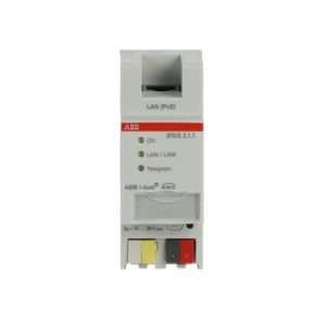
Use a line coupler when you need a clean TP line boundary (filtering, load isolation, commissioning scope) on a TP backbone or between TP lines. Prefer an IP router when the building spine is IP. Many mid-size jobs mix both: IP between cores, TP couplers inside a dense wing.
Can two power supplies share one topology segment?
No. One powered segment = one supply boundary. Extra supplies on the same bus without a proper line/area split complicate fault finding. If load is too high, upsize the supply class, split the segment with a coupler, or redesign device density — then recalculate per segment.
Conclusion: decide topology before you lock the BOM
A scalable topology is decided long before devices are ordered. Choosing the right line structure early protects commissioning time, keeps power budgets predictable, and prevents expensive redesign after award.
Whether you build around TP or IP, define segment boundaries first and let the BOM follow the topology — not the other way around. Name the pattern per zone, place every line coupler and IP router on the drawing, then run one current budget per powered segment.
- Name the SCALE-4 pattern per zone on one page.
- Fill the topology checklist until every cell is Y or an explicit Hold.
- Run one current budget per powered segment.
- Lock coupler / router order codes before actuator “equivalents” get creative.
Need to validate a topology before procurement? Use the Smartanix multi-brand catalog workspace to verify segment boundaries, line components, and power-related SKUs before locking order codes — start in System Components (couplers and routers also appear under Gateway). For a human pass on a tender sketch, request a design review via the contact CTA below.